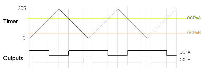
This step should always be done after all other settings.Before proceeding with this tutorial you should have the ESP32 add-on installed in your Arduino IDE. OC1A must be set to output because this does not happen automatically. And in this case, it is OC1A = PB1 = Arduino Pin 9. So we do not use the interrupt by means of an ISR, but directly control an Output Compare Pin. This allows us to define “Toggle OC1A on Compare Match” according to the table. Whether we use Mode 4 or 12 makes no difference, except in the definition of Top. The alternative would be prescaler 256 and Top 62499.

We take the 1024 as prescaler 104 as Top. Start\_value=65536-\frac-1\ \ \ \ with\ \ \ \ Top<65536Īgain, there are two possible combinations for the prescaler and Top. The counting frequency of TCNT1 is determined by the system clock and the prescaler: Overview of the WGM settings of the timer1 Clock Select Bits / Prescaler The choice of the WGM is always the basis for all further settings. In contrast to the Timer0 and Timer2, four WGM bits are available for the Timer1, i.e. Settings in TCCR1x Wave Form Generation Modes External Clock Pin T1Īs an alternative to the internal clock, you can attach an external clock to T1 (PD4, Arduino Pin 4). I will come back to this towards the end of this article. Thanks to the Input Capture function, the time sequence of fast events can be measured elegantly. The Input Capture pin corresponds to PB0 (Arduino Pin 8). The behavior of the Output Compare pins depends on the setting of the WGM1 bits and the Compare Output bits in TCCR1A and TCCR1B. Besides, I always refer to digital pins when I’m not writing anything else. When I speak of Arduino Pins below, I am referring to the Arduino UNO. The Timer1 has two Output Compare pins assigned to it, OC1A (PB1, Arduino UNO Pin 9) and OC1B (PB2, Arduino UNO Pin 10). Alternatively, you delete the bits by overwriting them with 0. Executing an interrupt vector deletes the bit. If the interrupts are enabled, the corresponding bits are set in TIFR1 if an interrupt is triggered. Timer/Counter1 Interrupt Flag Register TIFR1 TIMER1_COMPA_vect / TIMER1_COMPB_vect for Compare Match.For this, you pass the corresponding interrupt vectors to the ISR: If the respective interrupts are enabled, you can use them in Interrupt Service Routines (ISRs). In TIMSK1, you enable the interrupts for the Input Capture function (ICIE1), the Output Compare Matches (OCIE1B, OCIE1A), and the Timer Overflow (TOIE1). Timer/Counter1 Interrupt Mask Register TIMSK1 We discuss the consequences of this when we get to the PWM modes. Unlike OCR1A, ICR1 is not buffered, but is immediately overwritten. In these cases, the Input Capture Register function is disabled. Like OCR1A, ICR1 is the Top value in some WGM1 modes.The ICES1 bit mentioned above determines whether this should happen with the rising (ICES1 = 1) or falling edge (ICES1 = 0). If there is an event on ICP1, the counter reading of TCNT1 is written to ICR1.For all other bits please look at the data sheet of the ATmega 48 / 88 / 168 / 328 family.

ICES1, the Input Capture Edge Select Bit in TCCR1B, will be discussed together with the Input Capture function. Timer/Couter1 Control Register TCCR1A/B/C

Prescaler or external clock via the Chip Select Bits CS1x.Determination of what happens in case of a Compare Match (COM1xy Bits).Choice of Wave Form Generation Mode via the WGM1 Bits.The main settings are made in the Timer/Counter1 Control Registers TCCR1A, TCCR1B and TCCR1C. The registers are of course 16 bits like TCNT1. Depending on the setting and mode, a match (Compare Match) triggers certain actions. In the two Output Compare Registers OCR1A and OCR1B you can define values that are permanently compared with the TCNT1 register. Top is fixed or can be defined variably, depending on the mode. The lower limit is Bottom (zero), the upper limit is Top. The register counts corresponding to the system clock or it can be slowed down with a prescaler. The Timer/Counter1 Register TCNT1 is 16 bits. Structure and components of the Timer1 The registers of Timer1 Timer/Counter1 Register TCNT1 You don’t necessarily have to read part 1, but I’m going to explain fewer details in this part. Theoretically, it is very similar to the two 8-bit timers, but has greater flexibility and additional functions. In this second part I would like to go into the details of the 16 bit Timer1. In my last post I have explained the 8 bit timers of the Arduino UNO (or ATmega328P), namely Timer0 and Timer2.


 0 kommentar(er)
